
Nano Tomography (nanoCT)
NanoCT (Xradia Ultra 810 X-ray microscope) enables the non-destructive structural characterization of three-dimensional samples with resolution down to 50 nm. In this non-invasive X-ray microscopy technique, the sample is positioned in the focal spot of the X-ray beam and 2D X-ray radiographs of the sample are acquired at different angles. The transmitted X-rays are magnified by a Fresnel zone plate objective lens before reaching the X-ray camera (scintillator optically coupled to a CCD detector). For low absorption samples, a Zernike phase ring inserted into the beam path produce an edge enhancing phase contrast effect. Thus, the nanoCT can be adjusted for absorption and phase contrast and can be operated with a large field of view (FOV: 65 μm, resolution: 150 nm) or at high resolution (FOV: 16 μm, resolution: 50 nm). The 2D projections are then reconstructed which results in a visualization of the sample in 3D. Through further processing, the data can be segmented and quantified. The in situ nanomechanical testing device (with high mechanical stability and a maximum force of 0.8 N), allows to investigate the inner structure of materials under load. High quality nanotomography is very much dependent on the sample. Ideally, the sample is cylindrical, fits the field of view and its thickness is less than twice the X-ray absorption length of the sample material.
Details (nanoCT)
Features
- X-ray energy: 5.4 keV (Cr-anode)
- Tomography contrasts:
Absorption contrast
Zernike phase contrast - Resolution:
High resolution (HRES): 50 nm
Low resolution (LRES): 150 nm - Field of view: 16 µm (HRES), 65 μm (LRES)
- Scanning angle range: 180°, 140° for in situ
- in situ nanomechanical testing:
Maximum force: 0.8 N
Load modes: compression, indentation, tension
Limitations/constraints
- Sample needs to be stable under rotation and light wind
- Sample properties:
- Cylinder-shaped are preferred but not mandatory.
- Thickness should be less than twice the X-ray absorption length of its material (X-ray absorption length can be calculated here).
- Sample should fit the field of view (65 μm or 16 μm).
Application examples

Figure 1: Polymeric tetrahedral metamaterial scanned under load to different levels of strain using the in situ load stage. Sample scanned in phase contrast and large field of view (pixel size = 128 nm). (a)+(b) before load, (c)+(d) under load of 87.5 mN.
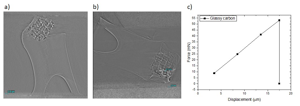
Figure 2: Glassy carbon tetrahedral metamaterial scanned under load to different levels of strain using the in situ load stage. Sample scanned in phase contrast and large field of view (pixel size = 128 nm). (a) under load of 8.5 mN, (b) under load of 52.8 mN, (c) Force x displacement curve.
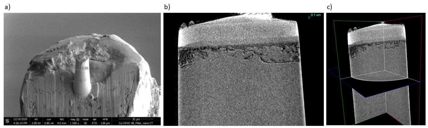
Figure 3: Cu sample scanned in absorption contrast with high resolution (resolution = 50 nm). (a) Pillar sample prepared by FIB (Image: Julia Rau), (b) 2D view, (c) 3D view.